This tutorial describes how to make a DecaWiNo.
Get the electronic parts
These parts are recommended to make a DecaWiNo:
- 1 PJRC Teensy 3.2 [buy]
- 1 DecaWave DWM1000 module [buy]
- 1 SMD RGB Common Cathode Leds
- 3 SMD 1206 resistors (330ohm)
- Standard HE13 male pins [buy]
- Standard HE13 female pins (optional) [buy]
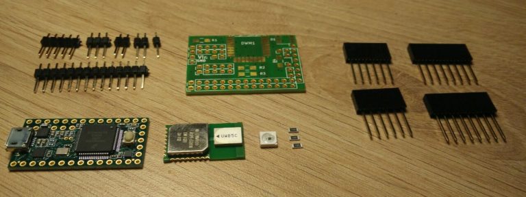
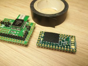
DecaWiNo parts
Get the hardware files and produce the PCB
The DecaWiNo is an open-source hardware board. It has been design with KiCad. Download the PCB files and launch the production. If your school or local fablab cannot produce PCB, you can order them on https://aisler.net/ (upload the DecaWiNo PCB sources and pay via Paypal).
Solder the DecaWiNo
The next step indicates how to solder the DecaWiNo.
|
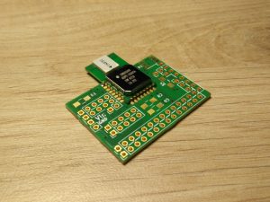
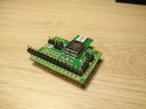
1. Place the DWM1000 on the PCB, adjust it over the footprint and solder one half-hole pin. |
|
2. Check the pin alignment and adjust it if necessary (this step is the trickiest), then solder the others pins. |
|
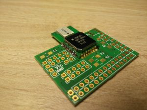
3. Solder the 330ohm resistor. |
|
4. Solder the HE13 male connectors. |
|
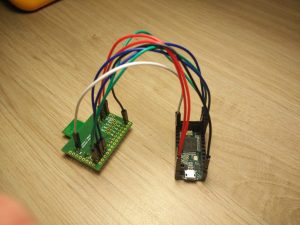
5. Optional: test the DWM1000 before soldering the Teensy by wiring signals GND, 3.3V, CLK, MOSI, MISO, CS and INT. Upload DecaDuino’s TWR example sketches and test. |
|
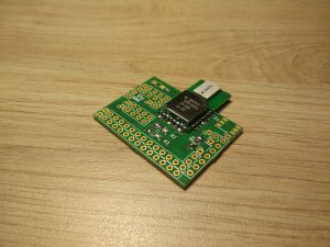
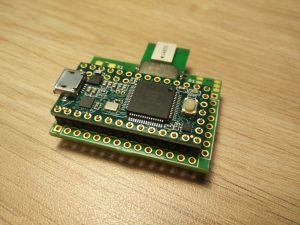
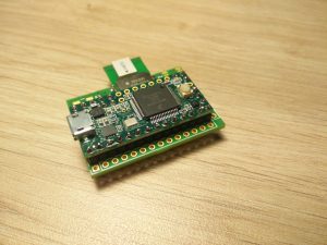
6. Put the Teensy 3.2 on the HE13 male pins. |
|
7. The teensy should not be in contact with the DWM1000 metal shield. If the plastic part of the HE13 male pins is not tall enough, pay attention to the next step |
|
8. Insulate the Teensy, for example with an adhesive plastic tape. Teensy pins 15 to 21 (included) and A11 are not used on DecaWiNo |
|
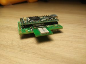
9. Put the Teensy and solder all pins. Solder the RGB LED. Solder the HE13 female pins. |
Test the DecaWiNo
Upload one of the DecaDuino's example sketches on the brand new DecaWiNo. The DecaDuino init() call must succed.
Follow the others tutorials on the DecaWiNo page.